Posted on Leave a comment

NASA Astronaut Mike Fincke Leaves NASA, Career Includes 4 Spaceflights

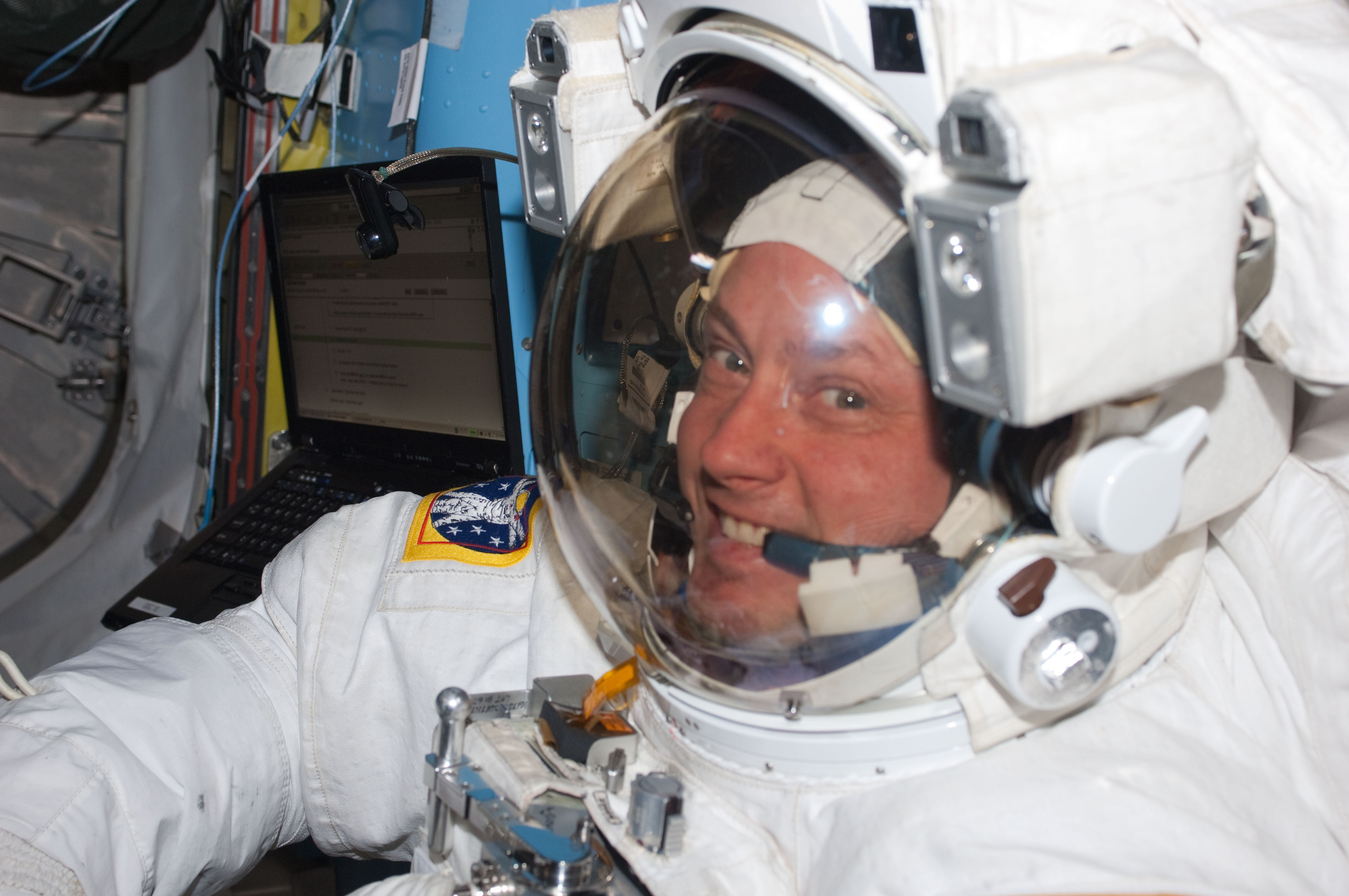
NASA astronaut Mike Fincke is pictured inside the International Space Station’s Quest airlock prior to the start of the third spacewalk for the STS-134 mission.
Credit: NASA

NASA astronaut Mike Fincke is departing the agency on Wednesday after 30 years of service. Throughout his career, he flew four missions, spent 549 days in space, and completed nine spacewalks in support of the International Space Station.

“Few people have had the opportunity to shape as many chapters of NASA’s history as Mike Fincke,” said NASA Administrator Jared Isaacman. “Over a remarkable career, Mike served our nation as a pilot, engineer, astronaut, and mentor. From long-duration missions aboard the International Space Station to helping prepare the Artemis generation, his contributions have helped position NASA for what comes next. The success we’re building on today is possible because of people like Mike, who dedicated their careers to moving our space program forward and preparing the next generation to carry the mission even further. I’d like to congratulate Mike on an incredible career and thank him for his decades of service to NASA, our nation, and the countless people who had the opportunity to learn from and fly alongside him.”

He ranks fourth among NASA astronauts in accumulated time in space, and his spacewalks total 48 hours and 37 minutes. Most recently, Fincke piloted NASA’s SpaceX Crew‑11 mission, which launched in August 2025 and returned in January. During the mission, he served as a flight engineer for International Space Station Expedition 73 and commander of Expedition 74.

Fincke joined NASA’s 16th astronaut class in 1996 and first flew to space in 2004 aboard Soyuz TMA‑4 in support of the space station’s Expedition 9. Serving as a science officer and flight engineer, he helped maintain station systems and performed four spacewalks. He returned to space in 2008 on Soyuz TMA‑13 as commander of Expedition 18, preparing the space station for its transition to six‑person crews at the time and completing two more spacewalks.

In 2011, Fincke flew on STS‑134, the final flight of space shuttle Endeavour. As mission specialist and robotic arm operator, he completed three spacewalks and helped deliver and install the Alpha Magnetic Spectrometer.

“Mike’s remarkable career reflects three decades of dedication to NASA’s mission and the advancement of human spaceflight,” said Vanessa Wyche, director of NASA’s Johnson Space Center in Houston. “From his time aboard the International Space Station to his commitment to mentoring the next generation, Mike has made an immense impact across our agency. His legacy of service, mentorship, and dedication to exploration will continue to inspire the generations to come.”

Throughout his career, Fincke bridged spacecraft development, flight testing, and mission operations. Early in the International Space Station Program, he helped test and integrate several of the station’s initial modules before launch. His flight experience spanned multiple generations of human spacecraft, including two missions aboard Soyuz, one aboard the space shuttle, and later piloting the SpaceX Dragon.

Fincke was a foundational contributor to NASA’s Commercial Crew Program. As chief of the Astronaut Office’s Commercial Crew Branch, he worked to ensure astronaut needs, crew safety, and human spaceflight experience informed development of the nation’s next generation of crewed spacecraft. He spent five years supporting Boeing’s Crew Flight Test program training as a crew member and backup pilot, contributing to flight software, systems integration, integrated testing, and spacecraft interfaces.

Fincke also supported station operations from the ground as a crew test support team member in Russia, a capsule communicator, or capcom, and crew procedures team lead. He helped translate complex engineering and operational requirements into clear instructions for crews working in orbit. His continuity across development, integration, mission support, and long‑duration flight gave him an end‑to‑end perspective on space station assembly and operation.

“Mike approached every assignment with experience, humility, and an unwavering focus on the mission,” said Scott Tingle, chief of the Astronaut Office at NASA Johnson. “Whether flying aboard the station, supporting crews from the ground, or helping shape the spacecraft that future crews will rely on, he consistently strengthened our team. His legacy is woven into the way we fly today.”

A native of Emsworth, Pennsylvania, Fincke holds bachelor’s degrees in aeronautics and astronautics and in Earth, atmospheric, and planetary sciences from the Massachusetts Institute of Technology, where he also studied in the Soviet Union through an exchange program with the Moscow Aviation Institute. He earned master’s degrees in aeronautics and astronautics from Stanford University and in planetary geology from the University of Houston, Clear Lake.

Fincke is a retired U.S. Air Force colonel and distinguished graduate of the U.S. Air Force Test Pilot School. He served as a space systems engineer and flight test engineer at Edwards and Eglin Air Force Bases and later as the U.S. flight test liaison to the Japanese‑U.S. XF‑2 fighter program at Gifu Air Base in Japan. He accumulated more than 2,000 flight hours in more than 30 aircraft types.

“After exactly 30 years, I am departing NASA, but I remain deeply committed to the work of exploration.” Fincke said. “NASA gave me the extraordinary privilege of serving alongside remarkable people, flying and helping develop spacecraft, and contributing to the International Space Station from its earliest days through command in orbit. I am profoundly grateful to my crewmates, the teams on the ground, our international partners, and the families who make this work possible. I am excited to carry those lessons forward and help prepare the next generation of engineers, explorers, and leaders. Together, we will return humanity to the Moon, travel to Mars, journey outward to the planets and moons beyond Earth, and someday reach for the stars – all while caring for Earth, the most beautiful planet in our solar system.”

To learn more about NASA’s astronauts and space exploration, visit:

https://www.nasa.gov/astronauts

-end-

Jimi Russell
Headquarters, Washington
202-358-1100
[email protected]

Anna Schneider
Johnson Space Center, Houston
281-483-5111
[email protected]

Details

Last Updated

Aug 12, 2026

Source: www.nasa.gov

Posted on Leave a comment

Casino en ligne en France : fonctionnement, risques et précautions

Les casinos en ligne reproduisent sur Internet des jeux traditionnellement proposés dans les établissements physiques. Ils peuvent offrir des machines à sous, des jeux de cartes, de la roulette ou des parties animées en direct. Leur accessibilité ne signifie cependant pas qu’ils sont légalement autorisés dans tous les pays.

Quels jeux sont autorisés en France ?

La réglementation française distingue les casinos physiques autorisés des jeux accessibles sur Internet. En ligne, les opérateurs agréés peuvent proposer des paris sportifs, des paris hippiques et du poker.

En revanche, les machines à sous et les jeux de table de casino ne sont pas autorisés en ligne. Un site accessible depuis la France peut donc rester illégal, même lorsqu’il affiche une licence internationale.

Les risques associés aux sites non autorisés

L’utilisation d’un casino en ligne non autorisé peut exposer le joueur à plusieurs problèmes. Il peut s’agir d’un refus de paiement, d’une fermeture soudaine du compte, d’un vol de données ou d’une absence de recours efficace en cas de litige.

Les autorités françaises peuvent également demander le blocage de plateformes proposant illégalement des jeux d’argent sur le territoire.

Reconnaître les principaux signaux d’alerte

Un site doit être considéré avec prudence lorsqu’il :

  • promet des gains garantis ;
  • exerce une forte pression pour effectuer un dépôt ;
  • dissimule ses conditions de retrait ;
  • réclame des frais imprévus pour libérer des gains ;
  • ne fournit aucune information vérifiable sur son exploitant ;
  • utilise abusivement le logo d’une autorité française.

La présence d’une licence étrangère ne remplace pas l’agrément exigé en France.

Protéger son budget

Aucune méthode ne garantit un bénéfice régulier aux jeux de hasard. Le résultat dépend principalement du hasard et l’opérateur conserve généralement un avantage mathématique.

Pour réduire les risques, il faut déterminer une limite de dépenses, ne jamais emprunter pour jouer et faire des pauses régulières. Les mineurs ne doivent jamais accéder aux jeux d’argent.

Lorsqu’une personne ressent une perte de contrôle, elle peut utiliser les dispositifs d’auto-exclusion ou demander une interdiction volontaire de jeux. Demander de l’aide rapidement permet de mieux protéger sa santé et sa situation financière.

Posted on Leave a comment

Lala Batters Hawaii


August 16, 2026
August 15, 2026

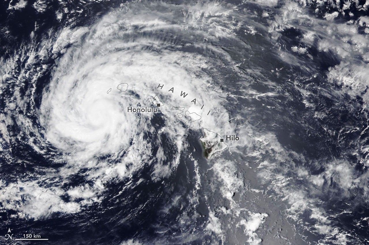
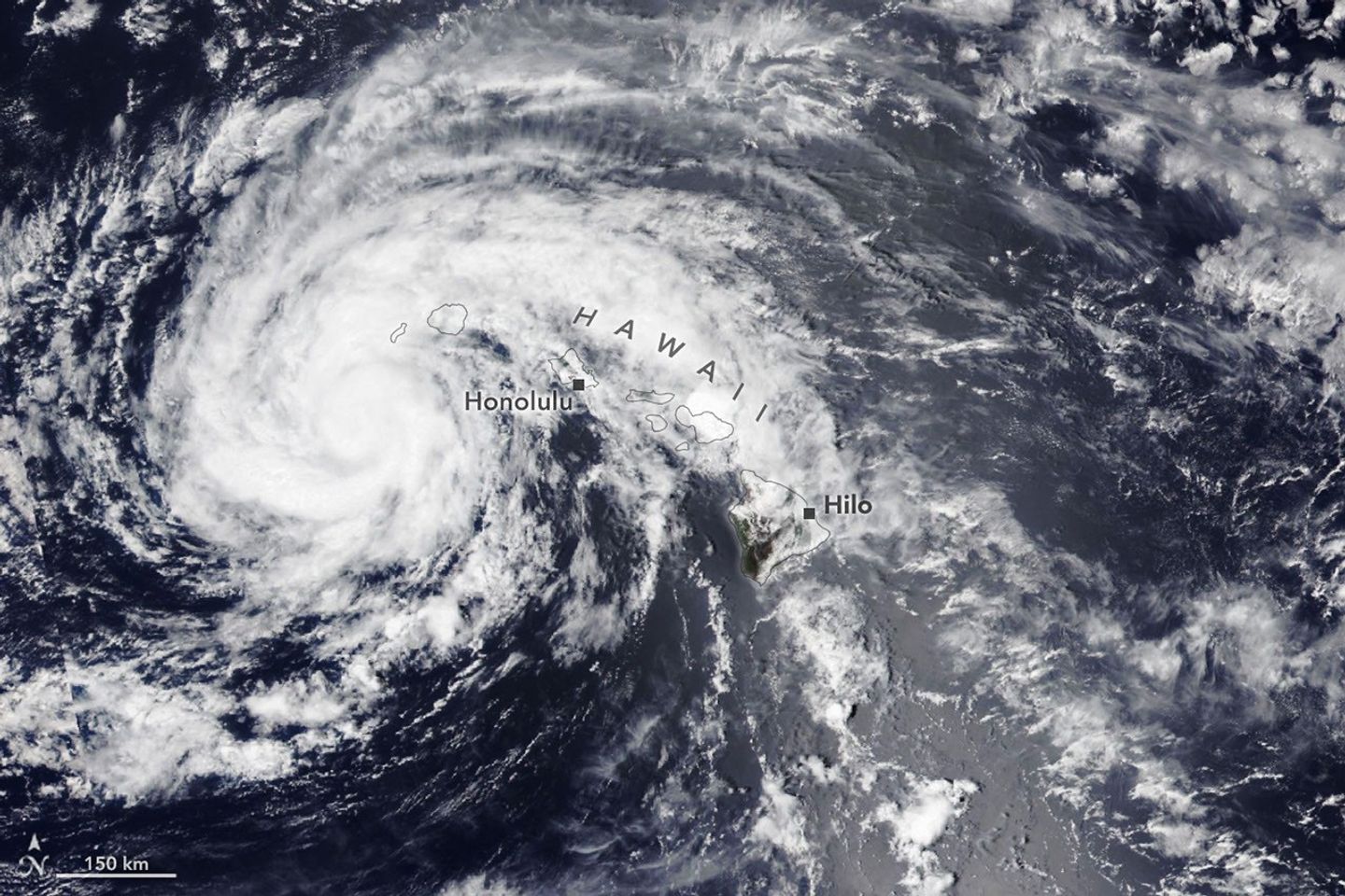
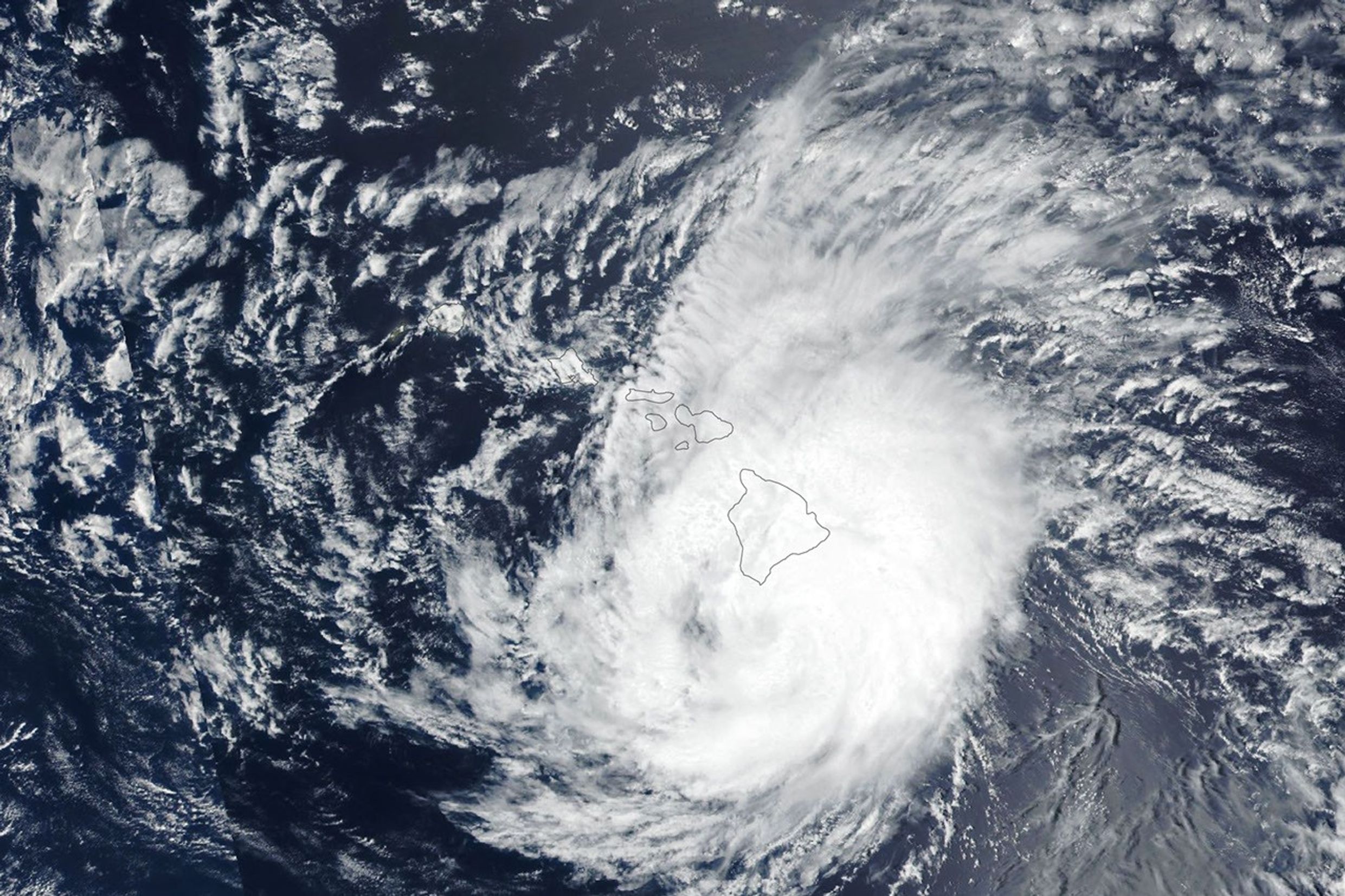
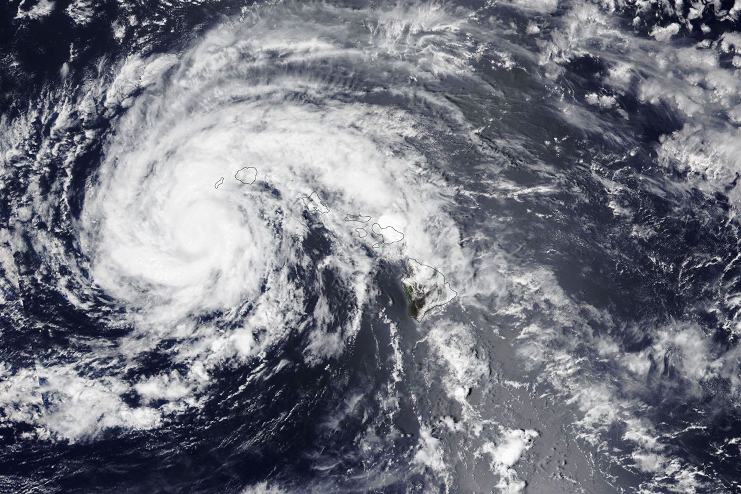
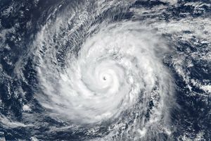
The spiraling clouds of a tropical storm are centered near the Hawaiian island of Kauaʻi.
NASA Earth Observatory / Lauren Dauphin

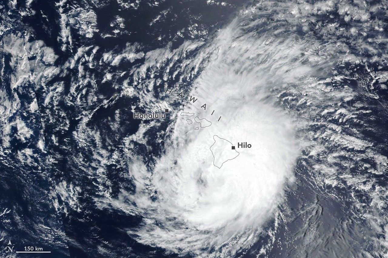
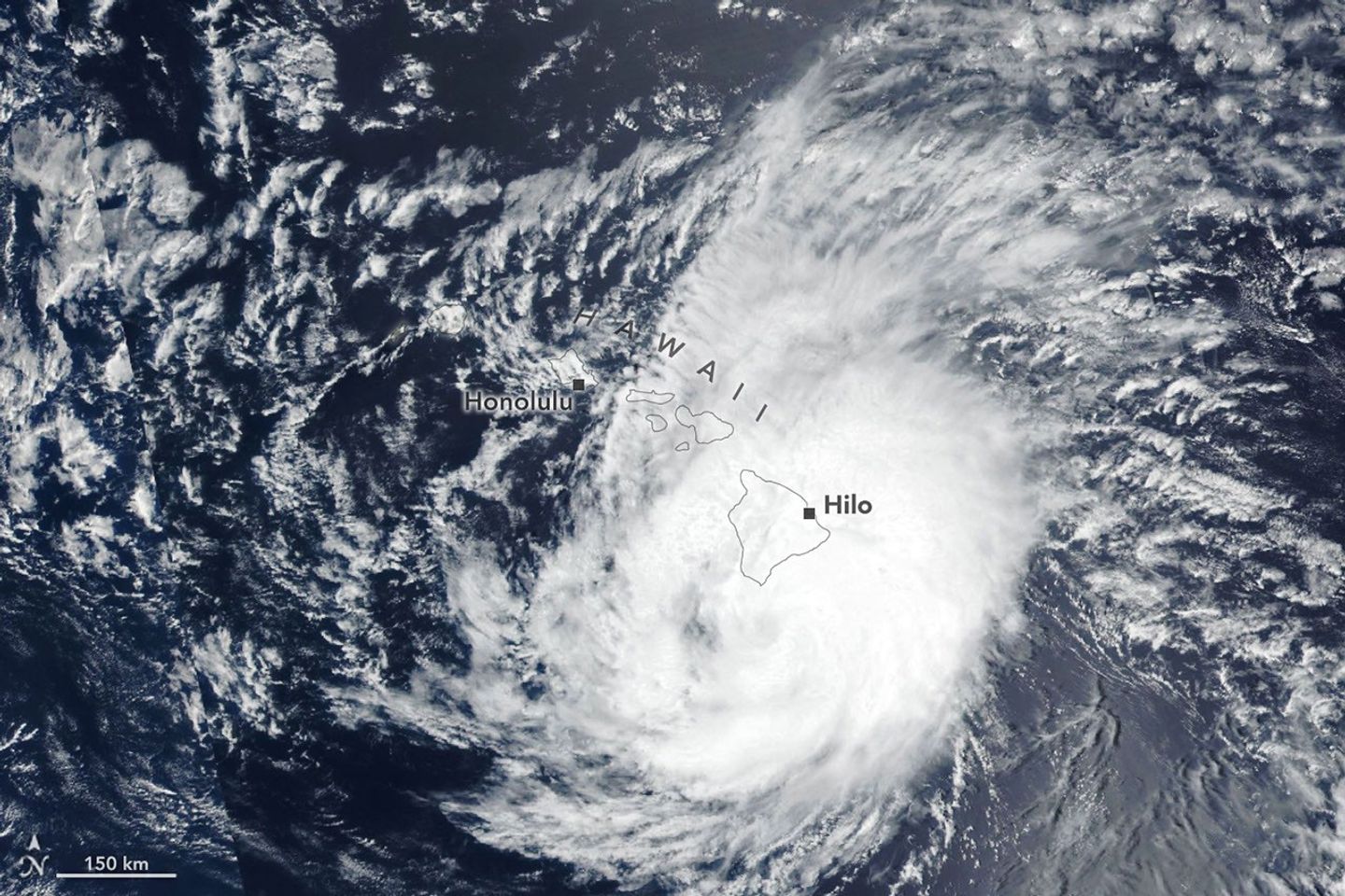
The spiraling clouds of a hurricane appear near the Hawaiian Islands. Its eye is just south of the Island of Hawaiʻi.
NASA Earth Observatory / Lauren Dauphin

The spiraling clouds of a tropical storm are centered near the Hawaiian island of Kauaʻi.
NASA Earth Observatory / Lauren Dauphin

The spiraling clouds of a hurricane appear near the Hawaiian Islands. Its eye is just south of the Island of Hawaiʻi.
NASA Earth Observatory / Lauren Dauphin


August 16, 2026

August 15, 2026


Lala skirts south of the Island of Hawaiʻi as a category 1 hurricane in the right image, acquired by the VIIRS (Visible Infrared Imaging Radiometer Suite) on the Suomi NPP satellite on August 15, 2026, at about 1:45 p.m. Hawaii Standard Time (23:45 Universal Time). The storm decreased in intensity while tracking northwest and was a tropical storm when the VIIRS on the NOAA-20 satellite captured the left image about 24 hours later. NASA Earth Observatory images by Lauren Dauphin.

The Island of Hawaiʻi narrowly avoided a direct landfall by Hurricane Lala in mid-August 2026. The storm nonetheless delivered serious damage as it passed just south of the island on August 15 (above, right) as a category 1 storm on the Saffir-Simpson wind scale.

Lala brought rainfall totals exceeding 20 inches (50 centimeters) to parts of the island, causing flash flooding and ongoing mudflow risks. The highest rainfall total for the storm—43.55 inches (110.6 centimeters) as of the morning of August 17—was recorded at Laupāhoehoe, on the coast northwest of Hilo. Lala downed trees, damaged bridges, and knocked homes off their foundations. Coastal areas were pummeled by large waves, while the summit of Mauna Kea, over 13,000 feet (4,000 meters) above sea level, experienced blizzard conditions.

By early afternoon on August 16, when the other image (left) was acquired, the storm had tracked northwest, roughly parallel to the island chain, and was southwest of Kauaʻi. Lala had decreased in intensity to a tropical storm, with sustained winds of 65 miles (105 kilometers) per hour, according to the National Hurricane Center.

While the Island of Hawaiʻi took the brunt of the storm, other islands also saw destructive effects. Strong winds caused widespread power outages, with more than 220,000 customers statewide without power as of the afternoon of August 16, according to news reports. Across the islands, wind and rain damaged infrastructure, and floodwaters and debris rendered roads impassable.

It has been an active tropical cyclone season in the Eastern Pacific so far in 2026, meteorologists note, consistent with what scientists expect during an El Niño, which has been underway as of mid-June. Warm water in the equatorial Pacific—the hallmark of El Niño—and the moisture and energy it transfers to the atmosphere help fuel nascent tropical storms. Lack of wind shear, another typical El Niño pattern in this region, also encourages tropical storms to develop and strengthen. The Atlantic hurricane season, in contrast, has been relatively calm, as greater wind shear over the Atlantic Ocean and Caribbean Sea during an El Niño inhibits hurricane formation by dissipating the upward motion of heat.

NASA Earth Observatory images by Lauren Dauphin, using VIIRS data from NASA EOSDIS LANCEGIBS/Worldview, and the Joint Polar Satellite System (JPSS). Story by Lindsey Doermann.

References & Resources

You may also be interested in:

Stay up-to-date with the latest content from NASA as we explore the universe and discover more about our home planet.

Tropical Storm Arthur

2 min read

The first named storm of the 2026 Atlantic hurricane season brought intense rainfall and the threat of flash flooding to…

Article

Typhoon Jangmi

2 min read

The sprawling storm promised to deliver torrential rain across a wide swath of southern Japan.

Article

Super Typhoon Sinlaku

3 min read

The violent storm aimed at the U.S. Northern Mariana Islands and Guam in mid-April 2026.

Article

Source: science.nasa.gov

Posted on Leave a comment

Copernicus Trajectory Design and Optimization System

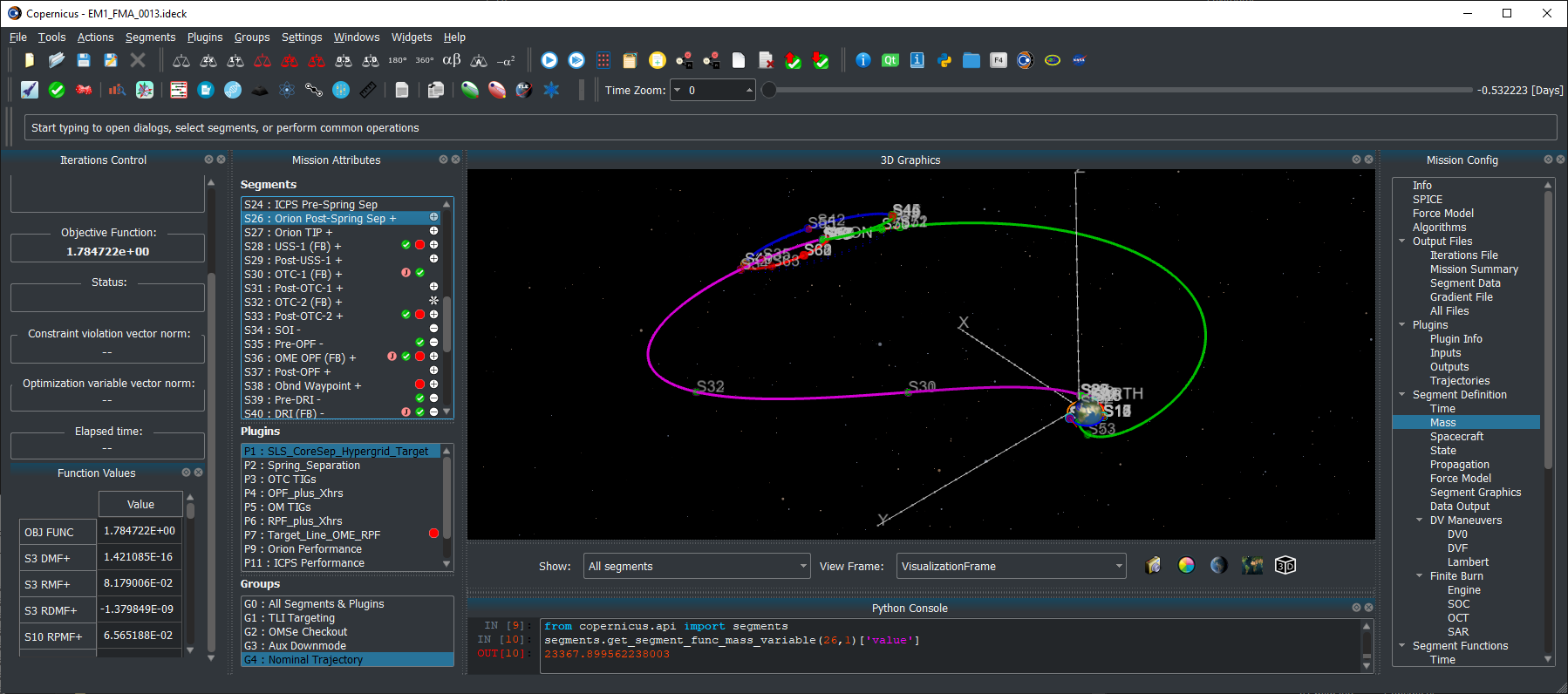
Screenshot of Copernicus with the Artemis I trajectory
NASA/JSC

Copernicus, a generalized spacecraft trajectory design and optimization system, is capable of solving a wide range of trajectory problems such as planet or moon centered trajectories, libration point trajectories, planet-moon transfers and tours, and all types of interplanetary and asteroid/comet missions.

Latest News

  • August 21, 2026: Copernicus Version 5.4.2 is now available. This is a bugfix release.
  • May 26, 2026: Copernicus Version 5.4.1 is now available. This is a bugfix release with a few new features.
  • March 23, 2026: Copernicus Version 5.4 is now available. This update includes numerous new features, enhancements, and bug fixes. This is also the first release with native support for Macs with Apple Silicon processors. Other updates include: New altitude and eclipse ramping/buffer engine model options; New propagation model to simulate a finite burn segment with a series of Kepler arcs & impulses; New circular restricted three-body problem (CR3BP) parameterization and propagation mode; New shadowing/eclipse model upgrades; New two-body rotating frame definition options; Many new GUI enhancements, usability upgrades, & improvements; Many enhancements and upgrades to the Copernicus Python API.
  • August 13, 2024: Copernicus Version 5.3.2 is now available.
  • December 18, 2023: Copernicus Version 5.3.1 is now available. This is a bugfix release.
  • November 15, 2023: Copernicus Version 5.3 is now available. This update includes many bug fixes and various new features and refinements. Including: a new Copernicus mission file format, updates to kernels, a significant expansion of the beta Python API, and various new integration methods. In addition, we have upgraded to Python 3.10, and all dependencies are now obtained via conda.
  • January 21, 2022: Copernicus Version 5.2 is now available. This update includes many bug fixes and various new features and refinements.
  • June 17, 2021: Copernicus was selected as winner of the 2021 NASA Software of the Year Award.
  • March 4, 2021: Copernicus Version 5.1 is now available. This update includes many bug fixes and various new features and refinements.
  • June 26, 2020: Copernicus Version 5.0 is now available. This is a significant update to Copernicus and includes: A new modern Python-based GUI that is now cross-platform and fully functional on Windows, Linux, and macOS, 3D graphics upgrades including antialiasing and celestial body shadowing, a new Python scripting interface, many other new features and options, and bug fixes.
  • May 1, 2018: Copernicus Version 4.6 is now available. The release includes the following changes: a new cross-platform JSON kernel file format, various new reference frame features, including new capabilities for user-defined reference frame plugins, and numerous bug fixes and other minor enhancements.
  • January 24, 2018: Copernicus Version 4.5 is now available. The new version includes a new experimental Mac version, faster exporting of segment data output files (including the addition of a new binary HDF5 format), some new GUI tools, new plugin capabilities, and numerous other new features and bug fixes.
  • October 1, 2016: Copernicus Version 4.4 is now available. The new version includes 3D graphics improvements and various other new features and bug fixes.
  • February 8, 2016: Copernicus Version 4.3 is now available. The new version includes updates to the plugin interface, a new differential corrector solution method, updated SPICE SPK files, updates to the Python interface, new training videos, as well as numerous other refinements and bug fixes.
  • July 21, 2015: Copernicus Version 4.2 is now available.  The update includes further refinements to the new plugin feature, as well as various other new features and some bug fixes.
  • April 13, 2015: Copernicus Version 4.1 is now available.  This update includes a new plugin architecture to enable extending Copernicus with user-created algorithms.  It also includes a new Python interface, as well as various other new features and bug fixes.
  • August 13, 2014: Copernicus Version 4.0 is now available.  This is an update to version 3.1, which was released in June 2012.  The new release includes many new features, bug fixes, performance and stability improvements, as well as a redesigned GUI, a new user guide, and full compatibility with Windows 7.  The update is recommended for all Copernicus users.

Development

The Copernicus Project started at the University of Texas at Austin in August 2001. In June 2002, a grant from the NASA Johnson Space Center (JSC) was used to develop the first prototype which was completed in August 2004. In the interim, support was also received from NASA’s In Space Propulsion Program and from the Flight Dynamics Vehicle Branch of Goddard Spaceflight Center. The first operational version was completed in March 2006 (v1.0). The initial development team consisted of Dr. Cesar Ocampo and graduate students at the University of Texas at Austin Department of Aerospace Engineering and Engineering Mechanics. Since March 2007, primary development of Copernicus has been at the Flight Mechanics and Trajectory Design Branch of JSC.

Request Copernicus

The National Aeronautics and Space Act of 1958 and a series of subsequent legislation recognized transfer of federally owned or originated technology to be a national priority and the mission of each Federal agency. The legislation specifically mandates that each Federal agency have a formal technology transfer program, and take an active role in transferring technology to the private sector and state and local governments for the purposes of commercial and other application of the technology for the national benefit. In accordance with NASA’s obligations under mandating legislation, JSC makes Copernicus available free of charge to other NASA centers, government contractors, and universities, under the terms of a US government purpose license.  Organizations interested in obtaining Copernicus should click here to request it.

Current Version

The current version of Copernicus is 5.4.1 (released May 26, 2026).

References

Publications about Copernicus

  • C. A. Ocampo, “An Architecture for a Generalized Trajectory Design and Optimization System”, Proceedings of the International Conference on Libration Points and Missions, June, 2002.
  • C. A. Ocampo, “Finite Burn Maneuver Modeling for a Generalized Spacecraft Trajectory Design and Optimization System”, Annals of the New York Academy of Science, May 2004.
  • C. A. Ocampo, J. Senent, “The Design and Development of Copernicus: A Comprehensive Trajectory Design and Optimization System”, Proceedings of the International Astronautical Congress, 2006. IAC-06-C1.4.04.
  • R. Mathur, C. A. Ocampo, “An Architecture for Incorporating Interactive Visualizations into Scientific Simulations”, Advances in the Astronautical Sciences, Feb. 2007.
  • C. A. Ocampo, J. S. Senent, J. Williams, “Theoretical Foundation of Copernicus: A Unified System for Trajectory Design and Optimization”, 4th International Conference on Astrodynamics Tools and Techniques, May 2010.
  • J. Williams, J. S. Senent, C. A. Ocampo, R. Mathur, “Overview and Software Architecture of the Copernicus Trajectory Design and Optimization System”, 4th International Conference on Astrodynamics Tools and Techniques, May 2010.
  • J. Williams, J. S. Senent, D. E. Lee, “Recent Improvements to the Copernicus Trajectory Design and Optimization System”, Advances in the Astronautical Sciences, 2012.
  • J. Williams, “A New Architecture for Extending the Capabilities of the Copernicus Trajectory Optimization Program”, Advances in the Astronautical Sciences, 2015, volume 156.
  • J. Williams, R. D. Falck, and I. B. Beekman. “Application of Modern Fortran to Spacecraft Trajectory Design and Optimization“, 2018 Space Flight Mechanics Meeting, AIAA SciTech Forum, (AIAA 2018-1451)
  • J. Williams, A. H. Kamath, R. A. Eckman, G. L. Condon, R. Mathur, and D. Davis, “Copernicus 5.0: Latest Advances in JSC’s Spacecraft Trajectory Optimization and Design System”, 2019 AAS/AIAA Astrodynamics Specialist Conference, Portland, ME, August 11-15, 2019, AAS 19-719
  • J. Williams, J. S. Senent, R. Mathur, and S. M. Stewart, “A History of Copernicus: The Origin, Development, and Evolution of JSC’s Spacecraft Trajectory Design and Optimization System”, AAS/AIAA Astrodynamics Specialist Conference, Boston, MA, August 2025, AAS 25-576.

Some studies that have used Copernicus

  • C. L. Ranieri, C. A. Ocampo, “Optimization of Roundtrip, Time-Constrained, Finite Burn Trajectories via an Indirect Method”, Journal of Guidance, Control, and Dynamics, Vol. 28, No. 2, March-April 2005.
  • T. Polsgrove, L. Kos, R. Hopkins, T. Crane, “Comparison of Performance Predictions for New Low-Thrust Trajectory Tools”, AIAA/AAS Astrodynamics Specialist Conference, August, 2006.
  • L. D. Kos, T. P. Polsgrove, R. C. Hopkins, D. Thomas and J. A. Sims, “Overview of the Development for a Suite of Low-Thrust Trajectory Analysis Tools”, AIAA/AAS Astrodynamics Specialist Conference, August, 2006.
  • M. Garn, M. Qu, J. Chrone, P. Su, C. Karlgaard, “NASA’s Planned Return to the Moon: Global Access and Anytime Return Requirement Implications on the Lunar Orbit Insertion Burns”, AIAA/AAS Astrodynamics Specialist Conference and Exhibit, August, 2008.
  • R. B. Adams, “Near Earth Object (NEO) Mitigation Options Using Exploration Technologies”, Asteroid Deflection Research Symposium, Oct. 2008.
  • J. Gaebler, R. Lugo, E. Axdahl, P. Chai, M. Grimes, M. Long, R. Rowland, A. Wilhite, “Reusable Lunar Transportation Architecture Utilizing Orbital Propellant Depots”, AIAA SPACE 2009 Conference and Exposition, September 2009.
  • J. Williams, E. C. Davis, D. E. Lee, G. L. Condon, T. F. Dawn, “Global Performance Characterization of the Three Burn Trans-Earth Injection Maneuver Sequence over the Lunar Nodal Cycle”, Advances in the Astronautical Sciences, Vol. 135, 2010. AAS 09-380
  • J. Williams, S. M. Stewart, D. E. Lee, E. C. Davis, G. L. Condon, T. F. Dawn, J. Senent, “The Mission Assessment Post Processor (MAPP): A New Tool for Performance Evaluation of Human Lunar Missions”, 20th AAS/AIAA Space Flight Mechanics Meeting, Feb. 2010.
  • J. W. Dankanich, L. M. Burke, J. A. Hemminger, “Mars sample return Orbiter/Earth Return Vehicle technology needs and mission risk assessment”, 2010 IEEE Aerospace Conference, March 2010.
  • A. V. Ilin, L. D. Cassady, T. W. Glover, M. D. Carter, F. R. Chang Diaz, “A Survey of Missions using VASIMR for Flexible Space Exploration”, Ad Astra Rocket Company, Document Number JSC-65825, April 2010.
  • J. W. Dankanich, B. Vondra, A. V. Ilin, “Fast Transits to Mars Using Electric Propulsion”, 46th AIAA/ASME/SAE/ASEE Joint Propulsion Conference & Exhibit, July 2010.
  • S. R. Oleson, M. L. McGuire, L. Burke, J. Fincannon, T. Colozza, J. Fittje, M. Martini, T. Packard, J. Hemminger, J. Gyekenyesi, “Mars Earth Return Vehicle (MERV) Propulsion Options”, 46th AIAA/ASME/SAE/ASEE Joint Propulsion Conference & Exhibit, July 2010, AIAA 2010-6795.
  • J. S. Senent, “Fast Calculation of Abort Return Trajectories for Manned Missions to the Moon”, AIAA/AAS Astrodynamics Specialist Conference, August 2010.
  • D. S. Cooley, K. F. Galal, K. Berry, L. Janes, G. Marr. J. Carrico. C. Ocampo, “Mission Design for the Lunar CRater Observation and Sensing Satellite (LCROSS)”, AIAA/AAS Astrodynamics Specialist Conference, August, 2010.
  • A. V. Ilin, L. D. Cassady, T. W. Glover, F. R. Chang Diaz, “VASIMR Human Mission to Mars”, Space, Propulsion & Energy Sciences International Forum, March 15-17, 2011.
  • J. Brophy, F. Culick, L. Friedman, et al., “Asteroid Retrieval Feasibility Study,” Technical Report, Keck Institute for Space Studies, California Institute of Technology, Jet Propulsion Laboratory, April 2012.
  • A. V. Ilin, “Low Thrust Trajectory Analysis (A Survey of Missions using VASIMR for Flexible Space Exploration – Part 2), Ad Astra Rocket Company, Document Number JSC-66428, June 2012.
  • P. R. Chai, A. W. Wilhite, “Station Keeping for Earth-Moon Lagrangian Point Exploration Architectural Assets”, AIAA SPACE 2012 Conference & Exposition, September, 2012, AIAA 2012-5112.
  • F. R. Chang Diaz, M. D. Carter, T. W. Glover, A. V. Ilin, C. S. Olsen, J. P. Squire, R. J. Litchford, N. Harada, S. L. Koontz, “Fast and Robust Human Missions to Mars with Advanced Nuclear Electric Power and VASIMR Propulsion”, Proceedings of Nuclear and Emerging Technologies for Space, Feb. 2013. Paper 6777.
  • J. Williams, “Trajectory Design for the Asteroid Redirect Crewed Mission”, JSC Engineering, Technology and Science (JETS) Contract Technical Brief JETS-JE23-13-AFGNC-DOC-0014, July, 2013.
  • J.P. Gutkowski, T.F. Dawn, R.M. Jedrey, “Trajectory Design Analysis over the Lunar Nodal Cycle for the Multi-Purpose Crew Vehicle (MPCV) Exploration Mission 2 (EM-2)”, Advances in the Astronautical Sciences Guidance, Navigation and Control, Vol. 151, 2014. AAS 14-096.
  • R. G. Merrill, M. Qu, M. A. Vavrina, C. A. Jones, J. Englander, “Interplanetary Trajectory Design for the Asteroid Robotic Redirect Mission Alternate Approach Trade Study”, AIAA/AAS Astrodynamics Specialist Conference, 2014. AIAA 2014-4457.
  • J. Williams, G. L. Condon. “Contingency Trajectory Planning for the Asteroid Redirect Crewed Mission”, SpaceOps 2014 Conference (AIAA 2014-1697).
  • J. Williams, D. E. Lee, R. J. Whitley, K. A. Bokelmann, D. C. Davis, and C. F. Berry. “Targeting cislunar near rectilinear halo orbits for human space exploration“, AAS 17-267
  • T. F. Dawn, J. Gutkowski, A. Batcha, J. Williams, and S. Pedrotty. “Trajectory Design Considerations for Exploration Mission 1“, 2018 Space Flight Mechanics Meeting, AIAA SciTech Forum, (AIAA 2018-0968)
  • A. L. Batcha, J. Williams, T. F. Dawn, J. P. Gutkowski, M. V. Widner, S. L. Smallwood, B. J. Killeen, E. C. Williams, and R. E. Harpold, “Artemis I Trajectory Design and Optimization”, AAS/AIAA Astrodynamics Specialist Conference, August 9-12, 2020, AAS 20-649

Source: www.nasa.gov

Posted on Leave a comment

New Next-Gen Dish Adds Muscle to NASA’s Deep Space Network

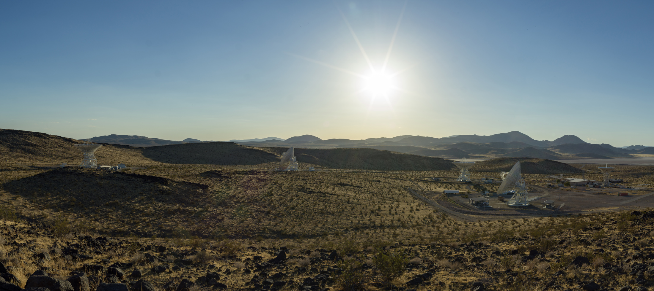
A wide desert landscape featuring several large white satellite dishes pointing toward a bright sun shining in a clear blue sky above distant mountain ranges.
Antennas soak in the summer Sun in August 2026 at the Deep Space Network’s Goldstone complex near Barstow, California, including the recently completed Deep Space Station 23 (shown in the foreground, to the right).
NASA/JPL-Caltech

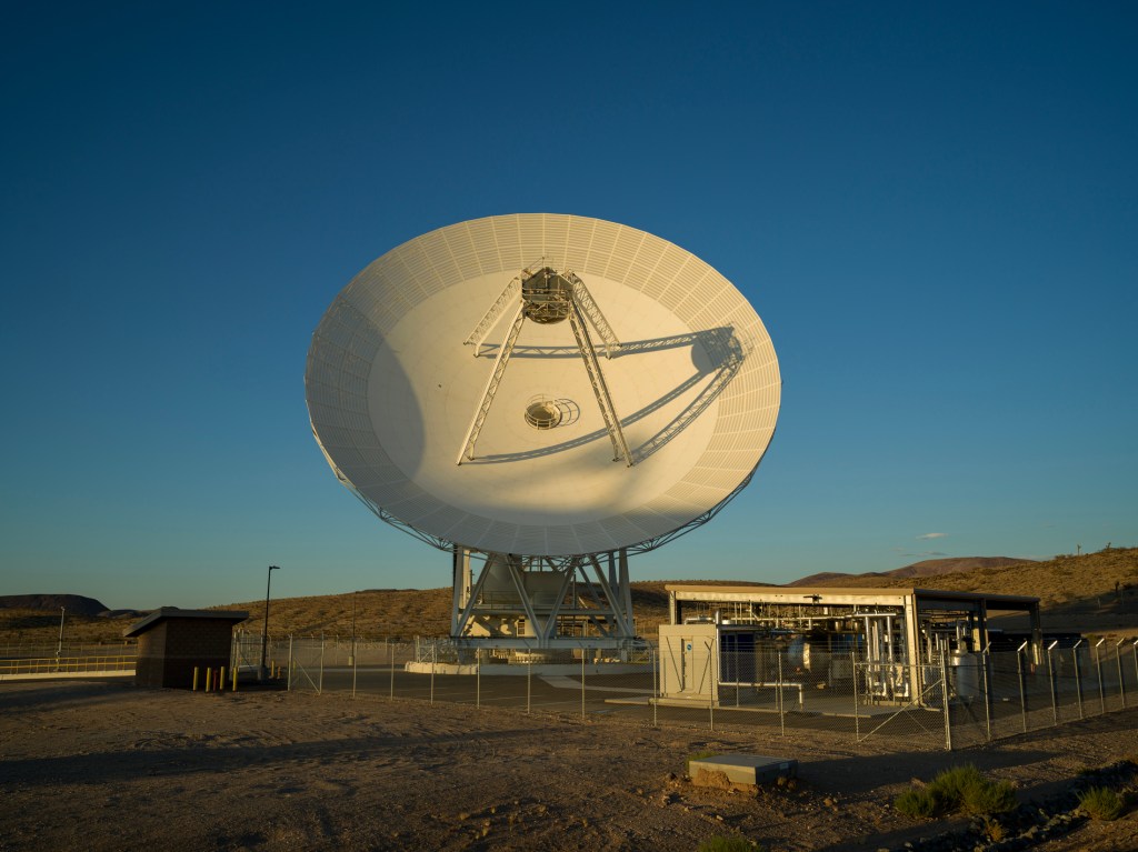
NASA’s Deep Space Network facility in California is marking the addition of a brand new 34-meter-wide (114-foot-wide) radio frequency antenna to the agency’s deep space communications and navigation system. The network uses giant dish antennas located at three global facilities to support more than 40 spacecraft exploring the solar system and interstellar space.

The new Deep Space Station 23 (DSS-23) is located at the Goldstone Deep Space Communications Complex, near Barstow, and is managed by NASA’s Jet Propulsion Laboratory in Southern California.

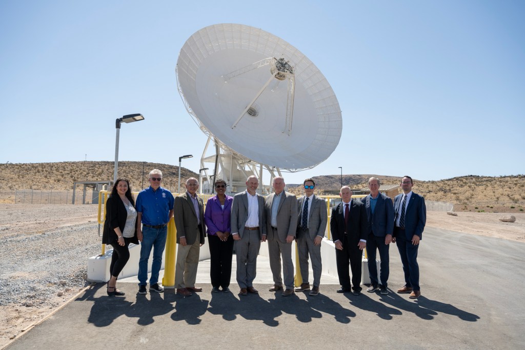
NASA leadership and personnel as well as dignitaries gathered at the complete DSS-23 antenna for a ceremonial ribbon cutting. It’s the latest to be added as part of the Deep Space Network’s Aperture Enhancement Project, which began in 2009 to upgrade and expand the network by adding six new 34-meter multifrequency beam-waveguide antennas. These versatile dishes can enhance many missions operating over different radio frequencies.

“By expanding the Deep Space Network, we are strengthening the communications foundation NASA needs for the bold missions ahead — from exploring more of the Moon than ever before to peering deeper into the solar system,” said James Kenyon, associate administrator of the Research and Technology Mission Directorate at NASA Headquarters in Washington. “This new antenna will help us deliver on our national goals for space exploration and push beyond the limits of what once seemed impossible.”

After completing a testing campaign from May through July to demonstrate its capabilities, the new DSS-23 began operations on Aug. 3, tracking NASA’s Chandra X-ray Observatory. Since then, it has been communicating with dozens of missions such as NASA’s Mars Reconnaissance Orbiter, Psyche, Juno, Voyager 1, and other robotic spacecraft in deep space.

“The addition of this next-generation antenna brings us closer to a completely modernized network that embraces advanced technology to ensure NASA’s leadership in deep space communications,” said Dave Gallagher, director of JPL. “After over 60 years of continuous operations supporting consequential missions, these upgrades prime the network for a new era of exploration. The teams that designed, planned, and built DSS-23 should be proud.”

Enhanced capabilities

Construction of DSS-23 began in February 2020. After the 133-ton metal reflector framework was placed and bolted atop the antenna’s pedestal in December 2024, engineers installed the panels to the framework that reflect radio frequency signals transmitted to and received from spacecraft. Then came the careful process of calibrating the antenna so it can work in concert with the rest of the network.

It is the fifth antenna at Goldstone (joining three 34-meter antennas and one 70-meter, or 230-foot, antenna) and the fifth enhancement project antenna to join the network, which includes antennas at the DSN’s Goldstone, Madrid, and Canberra, Australia, complexes. Multifrequency beam waveguide antennas direct signals down to a stable, climate-controlled underground room, rather than housing heavy, sensitive electronic equipment on the moving antenna dish. In addition to offering versatility, this design allows easy access for maintenance and upgrades to the system.

“The biggest challenge wasn’t actually constructing the antenna. It was transforming a complex collection of mechanical, electrical, software, radio frequency, and infrastructure systems into a single, mission-ready asset,” said Germaine Aziz, manager of the Deep Space Network Aperture Enhancement Project at JPL. “Every subsystem must be integrated, calibrated, and verified to operate with extraordinary precision and reliability before it can support NASA’s deep space missions.”

The enhancement project will be complete when a sixth enhancement-project antenna, Deep Space Station 33, comes online at the Canberra facility in 2029, bringing the total number of 34-meter antennas across the network to 13. The 34-meter antennas can be arrayed (combined and operated together) to provide an equivalent communications backup for each facility’s single 70-meter antenna, which, after more than 50 years of near-continuous operation, are getting increasingly costly to maintain and repair.

Managed by Caltech for NASA, JPL manages the agency’s Deep Space Network with the oversight of NASA’s SCaN (Space Communications and Navigation) Program within NASA’s Research and Technology Mission Directorate. More than 100 NASA and non-NASA missions rely on the Deep Space Network and Near Space Network. They include missions that support astronauts aboard the International Space Station and future Artemis missions, monitoring Earth, exploring the Moon, and exploring the solar system and beyond. 

For more information about the Deep Space Network, visit:

https://www.nasa.gov/communicating-with-missions/dsn

Source: www.nasa.gov

Posted on Leave a comment

NASA Selects Blue Origin as Mars Telecommunications Network Provider

NASA insignia.
Credit: NASA

NASA awarded Blue Origin a contract Tuesday to develop the agency’s Mars Telecommunications Network, a next-generation communications system that will enable reliable, high-bandwidth communications and navigation services for current and future Mars missions.

The firm-fixed-price contract has a maximum potential value of approximately $700 million to deliver a high-performance Mars telecommunications orbiter to NASA no later than Dec. 31, 2028.

Blue Origin will design, develop, integrate, launch, and operate the network as a part of the agency’s broader space communications and navigation infrastructure. The architecture will consist of a high-performance telecommunications spacecraft orbiting Mars, transmitting science data, imagery, navigation information, and critical mission communications for spacecraft operating on and around the planet.

The award marks a milestone in NASA’s strategy to expand communications and navigation services beyond Earth and the Moon, establishing the foundation for sustained exploration of Mars in the coming decades.

Under the Artemis program, NASA is sending astronauts to explore the Moon and prepare for missions to Mars. Robotic missions will pave the way for human exploration of the Red Planet, and as these missions expand, demand for data will continue to increase. To meet this need, NASA is pursuing a purpose-built network capable of supporting a growing number of missions while providing greater capacity, reliability, and operational flexibility.

The selection follows NASA’s request for proposal issued in May. As the agency increasingly taps commercial partners for transportation and communications services in Earth orbit and to develop the Moon Base, the Mars Telecommunications Network initiative similarly seeks to harness private-sector capabilities while enabling NASA to focus on exploration and scientific discovery.

The network, managed by NASA’s Space Communications and Navigation program, is expected to be operational at Mars by 2030 and will support both current and future missions to the Red Planet, as NASA ventures deeper into space.

For more information about NASA’s space communications efforts, visit:

https://www.nasa.gov/communicating-with-missions

-end-

Rob Margetta
Headquarters, Washington
202-358-0918
[email protected]

Rob Garner
Goddard Space Flight Center, Greenbelt, Md.
301-286-5687
[email protected]

Source: www.nasa.gov

Posted on Leave a comment

A Trio of Tropical Cyclones in the Pacific

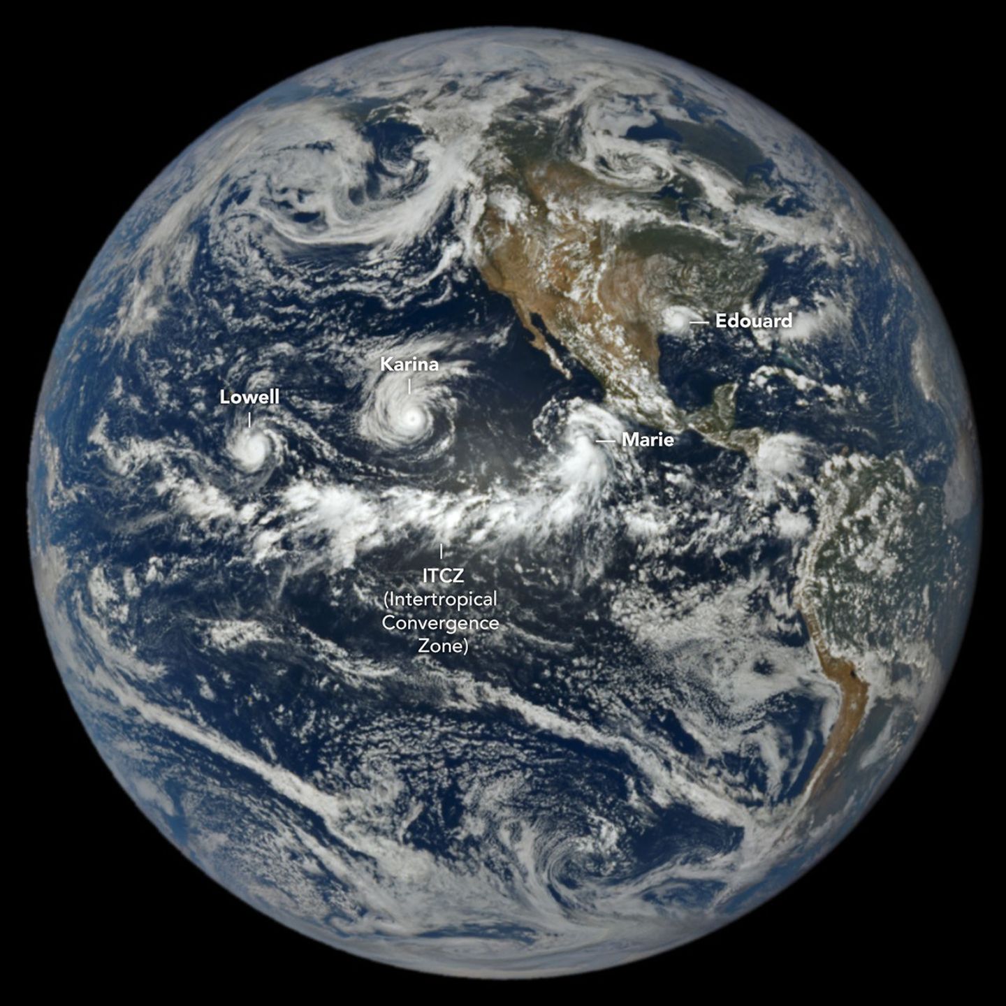
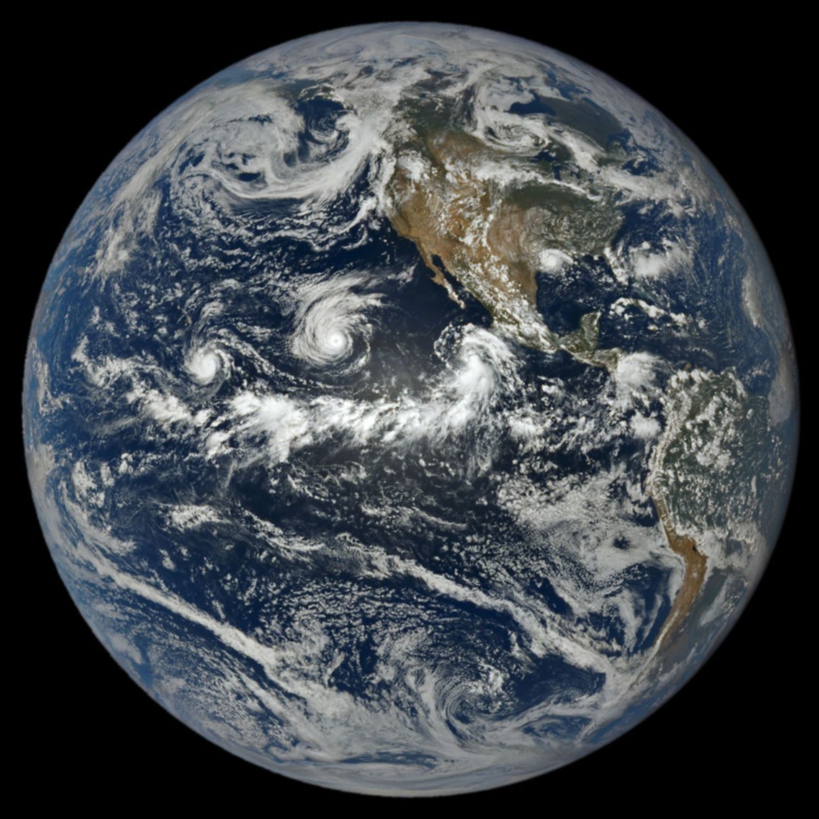
In a full-disk satellite view of Earth, three tropical cyclones—named Lowell, Karina, and Marie—swirl above the blue waters of the Pacific Ocean and to the west of Central America.

When hurricane forecasters released their seasonal outlooks in spring 2026, the El Niño brewing in the Pacific contributed to predictions of below-normal activity in the Atlantic basin but above-normal activity in the northeastern and central Pacific basins. In early September, near the climatological peak of hurricane season, those spring outlooks were on target, with the eastern Pacific buzzing with activity and the Atlantic notably quiet.

As of September 3, the Northeast Pacific had produced 15 named storms and six hurricanes, well above the norm for that point in the season. The Atlantic basin, meanwhile, laboring under unfavorable wind shear conditions, had produced just five named storms and no hurricanes. El Niño typically enhances hurricane activity in the eastern and central Pacific basins because of the unusually warm water temperatures it brings to those parts of the ocean. It tends to suppress hurricane activity in the Atlantic basin by shifting large-scale circulation patterns in a way that makes it harder to sustain storms there.

At 1:14 p.m. Pacific Daylight Time (20:14 Universal Time) on September 1, NASA’s EPIC (Earth Polychromatic Imaging Camera) on the DSCOVR (Deep Space Climate Observatory) satellite captured an image of three tropical cyclones churning simultaneously in the Pacific, along with one in the Atlantic. A band of clouds and thunderstorms associated with the Intertropical Convergence Zone (ITCZ) is visible to the south of the storms. The spacecraft was nearly 1 million miles from Earth and just shy of 93 million miles from the Sun when the image was acquired.

The trio of storms in the Pacific were Lowell, Karina, and Marie. Of the three, Lowell became the strongest, with winds reaching category 5 strength for several hours on September 2. Around the same time, Karina, spinning a few thousand kilometers to the east, achieved category 4 strength, a rare case of category 4 and 5 hurricanes occurring simultaneously in the area. Marie, spinning southwest of Baja California, was still a tropical storm when the image was acquired but was strengthening as it moved northwest.

In the Atlantic, Tropical Storm Edouard was visible to EPIC over Louisiana and Texas, shortly after the short-lived storm made landfall. It brought torrential rains and strong winds that downed trees and power lines. Some areas received 15 to 24 inches (38 to 61 centimeters) of rain, according to National Weather Service meteorologists.

As of September 3, the Atlantic basin’s total accumulated cyclone energy (ACE) index was 4.4, about 9 percent of normal for that date, according to statistics compiled by Colorado State University meteorologists. Meanwhile, the Northeast Pacific basin’s ACE was 130, about 50 percent above normal. The ACE index incorporates both the intensity and longevity of storms, making it easier to compare individual storms and seasons.

Several NASA Earth-observing platforms provide data that can aid in emergency preparedness before landfall and damage assessment and response afterward. Use the “Events” tab on NASA’s Worldview browser to track current hurricanes and explore related NASA data products.

NASA Earth Observatory image by Lauren Dauphin, using data from DSCOVR EPIC. Story by Adam Voiland.

References & Resources

You may also be interested in:

Stay up-to-date with the latest content from NASA as we explore the universe and discover more about our home planet.

Lala Batters Hawaii

3 min read

The powerful storm delivered extreme rainfall and damaging winds to the state, passing the Island of Hawaiʻi as a category…

Article

Tropical Storm Arthur

2 min read

The first named storm of the 2026 Atlantic hurricane season brought intense rainfall and the threat of flash flooding to…

Article

El Niño Is Underway

4 min read

Satellite observations of sea surface height indicated that the 2026 event continued to strengthen in early June.

Article

Source: science.nasa.gov

Posted on Leave a comment

APOD: 2026 September 4 – Na Uhane Mahoe Huki Pu i ke Ola

APOD

Astronomy Picture of the Day

Discover the cosmos! Each day a different image or photograph of our fascinating universe is featured, along with a brief explanation written by a professional astronomer.

Two spiral galaxies colliding.

Nā ʻUhane Māhoe Huki Pū i ke Ola

Explanation: Nā ʻUhane Māhoe Huki Pū i ke Ola, is the Hawaiian name given to this image of a pair of spiral galaxies locked in a mutual gravitational embrace. Some 200 million light-years distant toward the high flying constellation Pegasus their spectacular, galactic scale merger is captured in sharp detail in the image from the 8.1 meter Gemini North telescope on Maunakea, Hawai‘i. The galaxy pair, known as NGC 7253 and Arp 278, was chosen as a target, researched, and given an Hawaiian name by high school students in the joint Gemini Observatory and University of Hawaiʻi Project Hōkūlani internship program. The name translates to “The Twin Spirits Pulling Together Creating Life”. That’s both culturally and astronomically appropriate for galaxy collisions that trigger a cosmic maelstrom of star formation from galactic reservoirs of elemental building blocks of life. These merging galaxies are found within a region of Pegasus identified as the Hawaiian navigational constellation Ka Lupe o Kawelo.

APOD’s main NASA site is moving: From apod.nasa.gov to science.nasa.gov/apod
Tomorrow’s picture: chasing shadows

Date September 4, 2026
Credit: Image Credit: International Gemini Observatory / NOIRLab/NSF/AURA
Image Processing: J. Miller & M. Rodriguez (International Gemini Observatory/NSF NOIRLab),
T.A. Rector (University of Alaska Anchorage/NSF NOIRLab), D. de Martin & M. Zamani (NSF NOIRLab)
Authors & editors: Jerry Bonnell, Cecilia Chirenti, Robert Nemiroff, Keighley Rockcliffe
A service of: ASD at NASA / GSFC,
NASA Science Activation & Michigan Tech. U.

Source: science.nasa.gov

Posted on Leave a comment

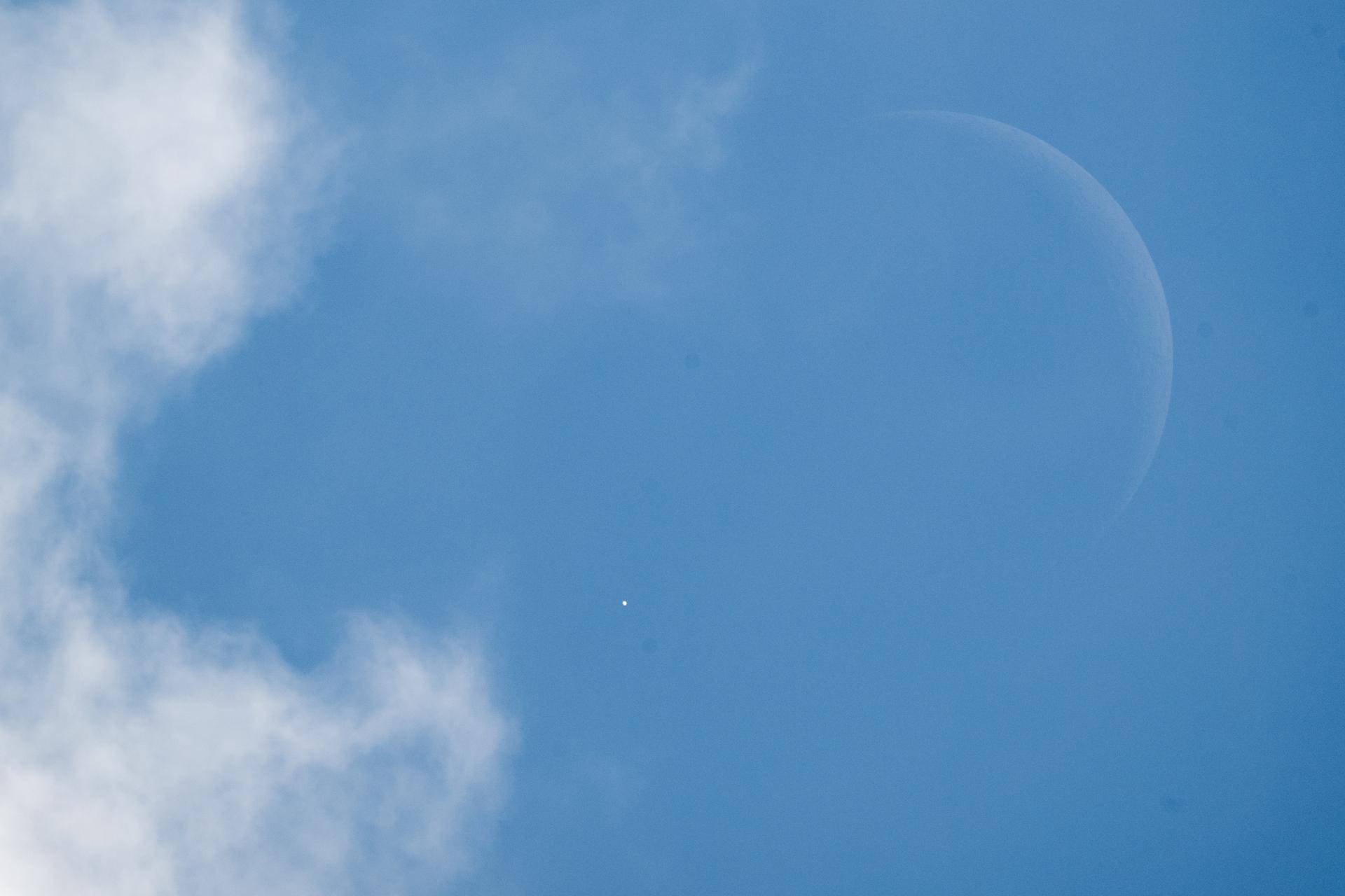
Lunar Occultation of Venus

Venus is seen as it disappears behind the Moon at the start of the occultation on June 17, 2026, from the Mary W. Jackson NASA Headquarters building in Washington
NASA/Joel Kowsky

On Wednesday, June 17, skywatchers across the United States—and parts of Canada—enjoyed a rare event: a daytime lunar occultation of Venus. A lunar occultation occurs when the Moon moves directly in front of another celestial object from our viewpoint on Earth, briefly hiding it from sight.

This time, the Moon slipped in front of Venus for the first of three occultations happening this year, creating a striking daylight moment for those who caught it. If you missed it, there will be two more opportunities to see Venus disappear behind the Moon in 2026: Sept. 14, visible from parts of Asia, Africa, Europe, and western Russia; and Nov. 7, visible from southern South America.

Source: www.nasa.gov
Posted on Leave a comment

NASA Hosts Virtual Artemis Webinar for Blind, Low-Vision Community

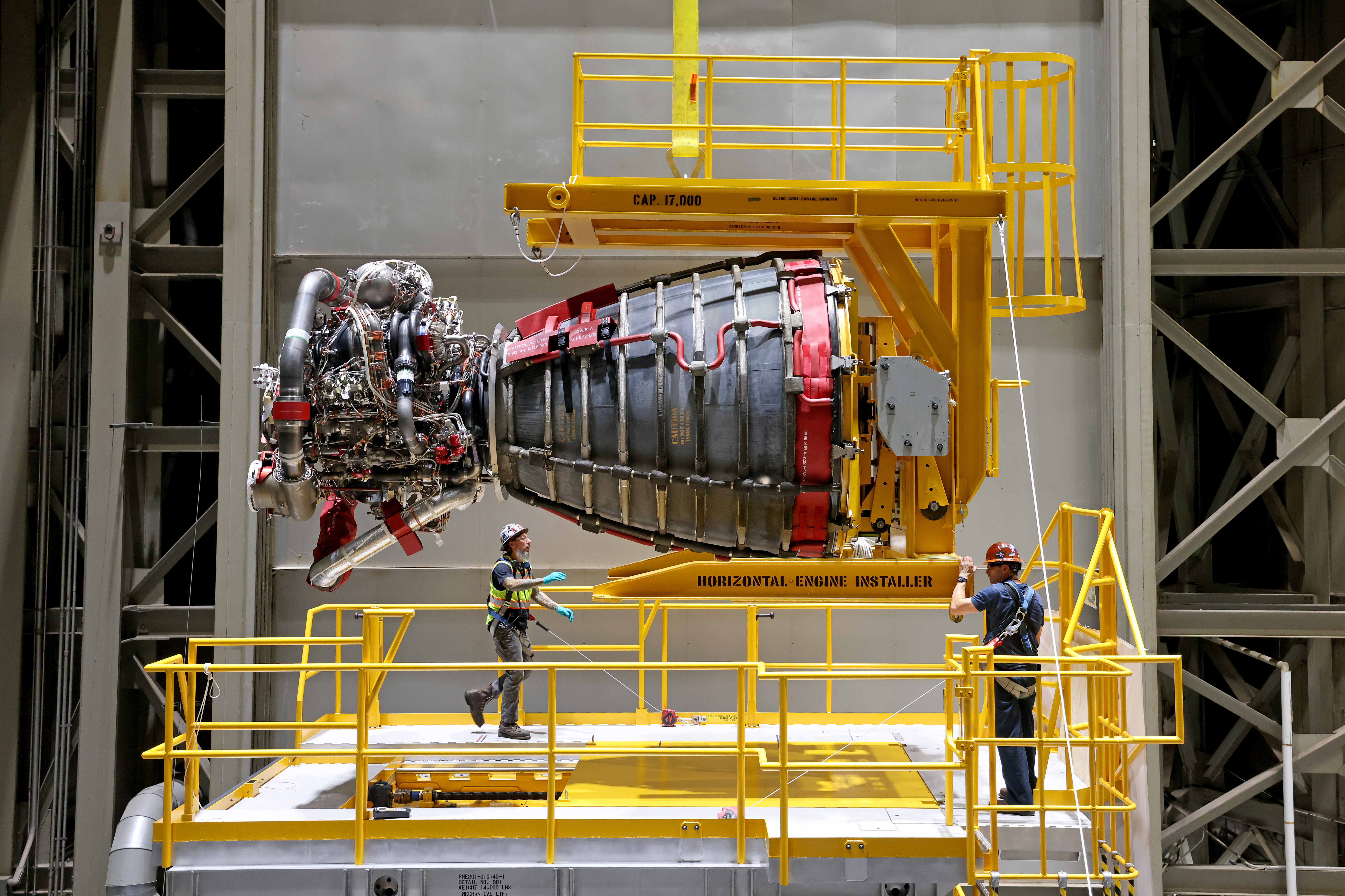
Two technicians at NASA’s Michoud Assembly Facility in New Orleans stand around one of the four RS-25 engines for the agency’s SLS (Space Launch System) rocket on Sept. 8, 2023. The RS-25 engine looks like a bell-shaped nozzle attached to a network of pipes. The engine is being lifted by the horizontal engine installer so it appears to be lying on its side. The RS-25 engine is about the size of a large pickup truck. The technicians are wearing hard hats and safety harnesses.
Credit: NASA/Michael Democker

NASA will host a virtual webinar at 2 p.m. EDT on Friday, Oct. 2, titled “The RS-25 Engine and the Future of Artemis Missions: An Accessible Webinar for the Blind and Low-Vision Community.” This webinar is open to the public, however it is tailored specifically for a blind and low-vision audience.

The webinar will last about two hours and include an audio-described video of an RS-25 engine test, a Q&A session with an Artemis engineer, and a panel about accessibility in space and science. The event will be hosted on the Zoom platform. 

Participants in the session include:

  • Dr. Kimberly Arcand, visualization scientist, NASA’s Chandra X-ray Observatory
  • Josh Greiner, test director, NASA’s Stennis Space Center in Bay St. Louis, Mississippi
  • Dr. Craig Moore, materials engineer, NASA’s Marshall Space Flight Center in Huntsville, Alabama
  • Dr. Robert Shelton, lead simulation engineer, NASA’s Johnson Space Center in Houston
  • Christine Malec, freelance writer and consultant

Those interested in attending the webinar must RSVP using this form by Friday, Sept. 25. Any questions can be directed to [email protected]. The details of the webinar will be emailed to registrants in the days leading up to the event.

NASA’s Artemis program will send astronauts on increasingly difficult missions to explore the Moon and establish a Moon Base on the lunar surface. For additional information on the Artemis missions, visit:

https://www.nasa.gov/artemis

Details

Last Updated

Sep 04, 2026

Related Terms

Source: www.nasa.gov